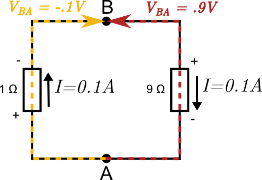
In a lecture at MIT by Professor Walter Lewin which can be seen at 8.02x – Lect 16 – Electromagnetic Induction, Faraday’s Law, Lenz Law, SUPER DEMO he demonstrates an interesting experiment whereby he connects two voltmeters on opposite sides of a loop containing two resistors of 1 Ohm and 9 Ohm. Inside the loop he generates an increasing magnetic field which produces an EMF of 1 Volt in the loop. The voltmeter on the right of the 9 Ohm resistor reads .9 Volt and the one on the left of the 1 Ohm resistor reads -.1 Volt. At first glance this seems like a paradox, the voltmeters are connected to the same two points and should therefor show the same value!

In the middle loop there is a varying magnetic field which increases in the direction towards you and at a moment in time it produces an EMF of 1V.

Using Faraday’s law of induction:
$$\oint \mathbf{E}\cdot \mathrm{d}\mathbf{l} = -\frac{\mathrm{d}\Phi}{\mathrm{d}t}$$
and Ohm’s law we can easily calculate the current in the loop. We assume a current going counterclockwise and go around the loop in the direction of the current. \(R_{\mathrm{left}}\cdot I+R_{\mathrm{right}}\cdot I = -\frac{\mathrm{d}\Phi}{\mathrm{d}t}\) or \(1\cdot I+9\cdot I = -1\) which gives \(I=-0.1\mathrm{A}\). So the actual direction of the current will be clockwise which also follows from Lenz’s law.

We can model the voltmeters as very large resistors and analyse the currents produced in the left and and the right one respectively. The magnetic field is so small outside of the middle loop that the EMF induced in the voltmeters can be neglected.

Using KVL and Ohm’s law in the left loop: $$ 10^7i_1 + (i_1+I) = 0 $$
And doing the same for the right loop: $$ 10^7i_2+9(i_2-I) = 0 $$
And finally we use Faraday’s law for the middle loop:
$$ 9(I-i_2)+(I+i_1)=1 $$
Solving these equations we get:
$$ \begin{align*} i_1 &\approx -1\cdot 10^{-8}\mathrm{A}\\ i_2 &\approx 9\cdot 10^{-8}\mathrm{A}\\ I &\approx 0.1\mathrm{A} \end{align*} $$
Notice that the current \(i_2\) through the right meter is 9 times larger and in opposite direction to the one on the left. The right meter will thus show a reading of \(R_{\mathrm{meter}}\cdot i_2 = 10^7\cdot 9\cdot 10^{-8} = 0.9\mathrm{V}\) and the left one \(R_{\mathrm{meter}}\cdot i_1 = 10^7\cdot -1\cdot 10^{-8} = -0.1\mathrm{V}\) just as demonstrated in the experiment by Professor Lewin.
This result sounds very non-intuitive but it all comes down to the fact that the electric field is non-conservative in the presence of a changing magnetic field, therefor the voltage between any two points is not uniquely defined and depend on the path one takes between the points. This is quite easy to see in the figure below where the current is going around in a clockwise direction. A positive charge moving from the point A up to point B through the right resistor moves against the electric field while a positive charge which moves from the same point A up through the left resistor to B moves with the electric field, hence the voltages must be of opposite polarity.
A detailed analysis is provided by Romer in his paper What do voltmeters measure? . Walter Lewin also discusses this problem in more depth in the following video Kirchhoff’s Loop Rule Is For The Birds.
The claim by Walter Lewin that KVL doesn’t hold in this situation and that you must use Faraday’s law instead has generated some controversy, see for instance Does Kirchhoff’s Law Hold? Disagreeing with a Master by Mehdi Sadaghdar and the followup video by Lewin To Agree or Not to Agree with the Master that is Not what Matters.